
The most used engineering terminology can be confusing to the average consumer. Understanding the common jargon used in Façade Engineering can help you communicate with your architect, engineer, or construction manager more effectively.
Rainscreen principle
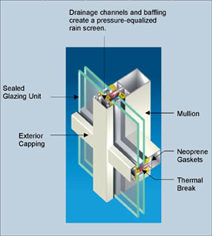
A rainscreen is an exterior wall detail where the siding (wall cladding) stands off from the moisture–resistant surface of an air barrier applied to the sheathing (sheeting) to create a capillary break and to allow drainage and evaporation. The rain screen is the siding itself[1] but the term rainscreen implies a system of building. Ideally the rain screen prevents the wall air/moisture barrier on sheathing from getting wet. In some cases a rainscreen wall is called a pressure-equalized rainscreen wall where the ventilation openings are large enough for the air pressure to nearly equalize on both sides of the rain screen,[2] but this name has been criticized as being redundant[3] and is only useful to scientists and engineers
Pressure Equalisation
Air pressure difference is one of the dominant forces for driving a rainwater into wall systems.[11] A rainscreen drainage plane that works as a predictable pressure equalization plane creates a separation (an air chamber) between the backside of a rainscreen and the exterior surface of the weather-resistant barrier that is installed on the exterior sheeting of the structural back up wall. This separation allows air contaminated with water vapor from all points in that wall system to exit the interior of the wall system. Moisture laden air that is allowed to pressurize will attempt to move to a lower pressure area that may be deeper into the interior of a wall detail.

http://buildingscience.com/documents/insights/bsi-004-drainage-holes-and-moderation
Air Infiltration
Air infiltration is the air which passes through the curtain wall from the exterior to the interior of the building. The air is infiltrated through the gaskets, through imperfect joinery between the horizontal and vertical mullions, through weep holes, and through imperfect sealing. The American Architectural Manufacturers Association (AAMA) is an industry trade group in the U.S. that has developed voluntary specifications regarding acceptable levels of air infiltration through a curtain wall. This limit is expressed (in the USA) in cubic feet per minute per square foot of wall area at a given test pressure. (Currently, most standards cite maximum of 0.06 CFM/sq ft at a pressure of at least 1.57 psf or higher as acceptable.) Testing is typically conducted by an independent third party agency using the ASTM E-783 standard.
Water penetration
- Water penetration is defined as water passing from the exterior of the building through to the interior of the curtain wall system. Sometimes, depending on the building specifications, a small amount of controlled water on the interior is deemed acceptable. Controlled water penetration is defined as water that penetrates beyond the inner most vertical plane of the test specimen, but has a designed means of drainage back to the exterior. AAMA Voluntary Specifications allow for controlled water penetration while the underlying ASTM E1105 test method would define such water penetration as a failure. To test the ability of a curtain wall to withstand water penetration in the field, an ASTM E1105 water spray rack system is placed on the exterior side of the test specimen, and a positive air pressure difference is applied to the system. This set up simulates a wind driven rain event on the curtain wall to check for field performance of the product and of the installation. Field quality control and assurance checks for water penetration has become the norm as builders and installers apply such quality programs to help reduce the number of water damage litigation suits against their work.
- ASTM E1105 Calibrated Spray Rack System is a field test instrument used by test agents to conduct water penetration testing on installed fenestration systems for Quality Control and Quality Assurance purposes. The spray rack must be calibrated to deliver water at a minimum rate of 8″ of rain per per hour/per square foot, or the equivalent of 5.0 US gallons per hour/square foot. The duration that water is sprayed continuously on the specimen is normally for a period of 15 or 20 minutes. The spray rack must be calibrated at least once every six months per the ASTM E1105 test method; calibrations may be necessary at smaller intervals should the spray rack system become damaged.
Deflection
One of the disadvantages of using aluminum for mullions is that its modulus of elasticity is about one-third that of steel. This translates to three times more deflection in an aluminum mullion compared to the same steel section under a given load. Building specifications set deflection limits for perpendicular (wind-induced) and in-plane (dead load-induced) deflections. It is important to note that these deflection limits are not imposed due to strength capacities of the mullions. Rather, they are designed to limit deflection of the glass (which may break under excessive deflection), and to ensure that the glass does not come out of its pocket in the mullion. Deflection limits are also necessary to control movement at the interior of the curtain wall. Building construction may be such that there is a wall located near the mullion, and excessive deflection can cause the mullion to contact the wall and cause damage. Also, if deflection of a wall is quite noticeable, public perception may raise undue concern that the wall is not strong enough.
Deflection limits are typically expressed as the distance between anchor points divided by a constant number. A deflection limit of L/175 is common in curtain wall specifications, based on experience with deflection limits that are unlikely to cause damage to the glass held by the mullion. Say a given curtain wall is anchored at 12 foot (144 in) floor heights. The allowable deflection would then be 144/175 = 0.823 inches, which means the wall is allowed to deflect inward or outward a maximum of 0.823 inches at the maximum wind pressure. However, some panels require stricter movement restrictions, or certainly those that prohibit a torque-like motion.
Deflection in mullions is controlled by different shapes and depths of curtain wall members. The depth of a given curtain wall system is usually controlled by the area moment of inertia required to keep deflection limits under the specification. Another way to limit deflections in a given section is to add steel reinforcement to the inside tube of the mullion. Since steel deflects at ⅓ the rate of aluminum, the steel will resist much of the load at a lower cost or smaller depth.
Louvers
A louver is provided in an area where mechanical equipment located inside the building requires ventilation or fresh air to operate. They can also serve as a means of allowing outside air to filter into the building to take advantage of favourable climatic conditions and minimize the usage of energy-consuming HVAC systems. Curtain wall systems can be adapted to accept most types of louver systems to maintain the same architectural sightlines and style while providing the necessary functionality.
Windows and vents
Most curtain wall glazing is fixed, meaning there is no access to the exterior of the building except through doors. However, windows or vents can be glazed into the curtain wall system as well, to provide required ventilation or operable windows. Nearly any window type can be made to fit into a curtain wall system.
Fire safety
Beam
A structural member, usually horizontal, with a main function to carry loads cross-ways to its longitudinal axis. These loads usually result in bending of the beam member. Examples of beams are simple, continuous, and cantilever.
Beam-Column
This is a structural member whose main function is to carry loads both parallel and transverse to the longitudinal axis.
Cantilever
Cantilever refers to the part of a member that extends freely over a beam, which is not supported at its end.
Collateral Load
Collateral load is additional dead loads (not the weight of people and not the weight of the building itself), such as plumbing, duct work, ceilings, and other components of the structure.
Column
A column is a main vertical member that carries axial loads from the main roof beams or girders to the foundation parallel to its longitudinal axis.
Continuity
Continuity is the term given to a structural system describing the transfer of loads and stresses from member to member as if there were no connections.
Damping
Damping is the rate of decay of amplitude for floor vibrations.
Dead Load
Dead load describes the loads from the weight of the permanent components of the structure.
Deflection
Deflection is the displacement of a structural member or system under a load.
Dynamic Load
This type of load varies over time.
Footing
A footing is a slab of concrete under a column, wall, or other structural to transfer the loads of the member into the surrounding soil.
Foundation
A foundation supports a building or structure.
Header
A member that carries other supporting members and is placed between other beams.
Joist
A structural load-carrying member with an open web system which supports floors and roofs utilizing hot-rolled or cold-formed steel and is designed as a simple span member.
Pascal Pa Kilo Pascal = 1000Pa (KPa)
The pascal can be expressed using SI derived units, or alternatively solely SI base units, as:

where N is the newton, m is the metre, kg is the kilogram, and s is the second.[5]
One pascal is the pressure exerted by a force of magnitude one newton perpendicularly upon an area of one square metre.
Live Load
Non-permanent loads on a structure created by the use of the structure.
Load
An outside force that affects the structure or its members.
Modulus of Elasticity (E)
The value is usually 29,000 ksi for structural steels and is also called Young’s Modulus. It calculates the slope of the straight-line portion of the stress-strain curve in the elastic range.
Moment
Moment is the tendency of a force to cause a rotation about a point or axis which in turn produces bending stresses.
Moment of Inertia (I)
A measure of the resistance to rotation offered by a member’s geometry and size.
Seismic Load
Loads produced during the seismic movements of an earthquake.
Shear
Forces resulting in two touching parts of a material to slide in opposite directions parallel to their plane of contact.
Span
The distance between supports.
Structural Steels
Steels suitable for load-carrying members in a structure.
Strut
A structural brace that resists axial forces.
Stud
A vertical wall member used to attach other structures, such as walls.
Torsion Loads
A load that causes a member to twist about its longitudinal axis. A couple or moment in a plane perpendicular to the axis produces simple torsion.
Wind loads
Wind load
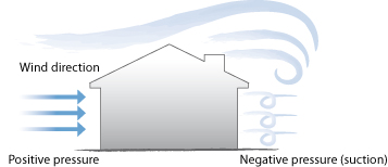
Wind load acting on the building is the result of wind blowing on the building. This wind pressure must be resisted by the curtain wall system since it envelops and protects the building. Wind loads vary greatly throughout the world, with the largest wind loads being near the coast in hurricane-prone regions. For each project location, building codes specify the required design wind loads. Often, a wind tunnel study is performed on large or unusually shaped buildings. A scale model of the building and the surrounding vicinity is built and placed in a wind tunnel to determine the wind pressures acting on the structure in question. These studies take into account vortex shedding around corners and the effects of surrounding area
These most used structural engineering terminology definitions provide a baseline understanding of engineering jargon for the average consumer. Detailed definitions can be obtained from visiting a professional engineering website or professional journal.
for further reading please read link below:

Very good explanations above. Thank you. Andi Alpert Ziegelman, Haifa, Iisrael
LikeLike